Controller Area Network classic (CAN CC)
CAN CC data link layer is internationally standardized in ISO 11898-1. It is the dominating serial network for embedded control systems in passenger cars, but is not limited to this application field. It features:
- Multi-drop capability, which allows the design of distributed and redundant communication systems.
- Broadcast communication, which reduces bandwidth requirements and favors design flexibility.
- Sophisticated error detection functions and automatic re-transmission of erroneous frames, which leads to a high-reliable communication.
- Unique fault confinement, which guarantees network-wide data consistency.
The conformance test plan for the CAN CC data link layer is specified in ISO 16845-1. It allows to test CAN CC data link layer implementations on compatibility. For CAN CC, there are different physical medium access (PMA) sub-layers standardized in order to meet different application requirements. The most used and generic one is the so-called CAN high-speed PMA, which is standardized in ISO 11898-2. Since 2016, this standard also includes the low-power and the selective wake-up options.
Principles of data exchange

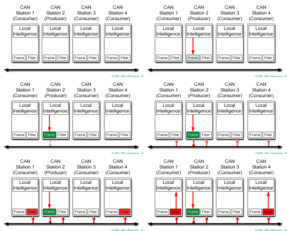
CAN CC is based on the “broadcast communication mechanism”. Every CAN CC data frame provides an identifier, which should be unique within the entire network. It indicates the content and defines the network access priority. This is important in case several network participants compete for network access (network arbitration). This approach enables content addressing as well as node addressing, depending on the chosen network layer. As a result, a high degree of system and configuration flexibility is achieved.
It is easy to add CAN CC nodes to an existing network without making any hardware or software modifications to the present CAN CC nodes as long as the new CAN CC nodes are receivers only. This allows for a modular concept, permits the reception of multiple data, and the synchronization of distributed processes. Furthermore, data transmission is not based on the availability of specific types of network participants. Thus, servicing and upgrading the network is rather simple.
Real-time data transmission

In real-time processing, the urgency of data to be exchanged over the network can differ significantly: a rapidly changing dimension, e.g. engine load, is transmitted more frequently and therefore with less delays than other dimensions, e.g. engine temperature.
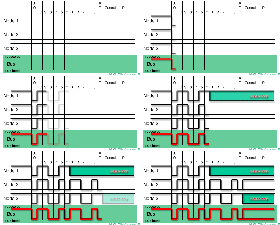
Priorities, at which data frames are transmitted compared to other less urgent data frames, are determined by the assigned CAN identifier (CAN-ID). The priorities are allocated during system design. The CAN identifier consists of either an 11-bit or a 29-bit binary value. The lowest value has the highest priority; the higher the value of the identifier, the lower is the priority.
In case several data or remote frames compete for network access at the very same time, the network access is negotiated by the bit-wise comparison of the CAN identifiers of the competing data or remote frames. This mechanism is called bit-wise arbitration. The involved network participants (nodes) observe the signal level bit by bit at the configured sample point. This happens in accordance with the wired-and mechanism, by which the dominant state overwrites the recessive state. All those nodes with recessive transmission and dominant observation lose the competition for network access. All those "losers" automatically become receivers of the currently transmitted CAN data frame, with the highest priority. They attempt transmitting their CAN data frame after the current transmission is finalized and the network is available again.
Thus, transmission requests are handled in the order of their importance for the system as a whole. This proves especially advantageous in overload situations. Since network access is prioritized on the basis of the CAN data frame’s identifier, it is possible to guarantee low individual latency times in real-time systems.
CAN CC data frame formats

The CAN CC protocol supports two CAN data frame formats. Basically, they only differ in the length of the CAN identifier. The “CAN CC base frame format (CBFF)” supports a length of 11 bit for the CAN identifier, and the “CAN CC extended frame format (CEFF)” supports a length of 29 bit for the CAN identifier.
CAN CC base frame format
A CAN data frame starts with the “start of frame” (SOF) bit. By means of this bit, all connected nodes in the network are synchronized for the duration of one CAN data frame transmission. It is followed by the "arbitration field", which provides the CAN identifier and the "remote transmission request (RTR)" bit. The RTR bit is used to distinguish between the CAN data frame and the CAN remote frame. The following "control field" contains the "identifier extension (IDE)" bit as well as the "data length code (DLC)". The IDE bit allows distinguishing between the CAN CC base frame format and the CAN CC extended frame format. It is also subject of the arbitration process. This means a data frame in CBFF wins arbitration against a data frame in CEFF using the very same values for the first 11 CAN-ID bits.
The DLC indicates the size of the following "data field" in multiples of one byte. In a remote frame, the DLC contains the number of requested data bytes. The "data field" provides the application data, which may vary between zero and up to eight data bytes. The integrity of data and remote frames is guaranteed by the "cyclic redundancy check (CRC)" sum. In case a data frame has been transmitted correctly, up to this point, all receiving nodes confirm the correct reception in the "acknowledge (ACK) field" by transmitting a dominant bit in the ACK slot bit. The end of the data and remote frames is indicated by the "end of frame (EOF)" field. The 3-bit intermission field is the minimum number of bits separating consecutive data or remote frames. Unless another connected node starts transmitting, the network remains idle after this. The intermission field is part of the inter-frame space (IFS), which may contain also the bus idle time and the 8-bit suspend transmission in case of an error passive node.
CAN CC extended frame format
The difference between the extended frame format and the base frame format is the length of the used CAN identifier. The 29-bit identifier is made up of the 11-bit identifier (“base identifier”) and an 18-bit extension (“identifier extension”). The distinction between the CAN CC base frame format and CAN CC extended frame format is made by using the IDE bit. In case of the CAN CC extended frame format (29-bit CAN-ID) the IDE bit is transmitted recessively; in case of CAN CC base frame format (11-bit CAN-ID), dominantly. In comparison to data frames in CBFF, the CAN CC extended frame format has some trade-offs. The network latency time is longer (at least 20 bit times), data frames in extended format require more bandwidth (about 20%), and the error detection performance is lower (because the chosen polynomial for the 15-bit CRC is optimized for frame length up to 112 bit).
Since 2003, all CAN CC implementations shall be capable to handle both CAN CC data frame formats. Older implementations may either only accept the CAN CC base frame format, or may just tolerate the CAN CC extended frame format.
Detecting and signaling errors
The CAN data link layer implements five error detection mechanisms to achieve highest reliability:
- Cyclic redundancy check (CRC): The CRC safeguards the CAN frame by adding a frame check sequence (FCS) in the CRC field. At the receiver this FCS is recomputed and tested against the received FCS. If they do not match, there has been a CRC error.
- Frame check: This mechanism verifies the structure of the transmitted frame by checking the bit fields against the fixed format and the frame size. Errors detected by frame checks are designated "format errors".
- ACK errors: Receivers of CAN frames acknowledge the received frames. If the transmitter does not receive an acknowledgement an ACK error is indicated.
- Bit monitoring: The ability of the transmitter to detect errors is based on the monitoring of network signals. Each node that transmits also observes the signal level and thus detects differences between the bit sent and the bit received. This permits reliable detection of global errors and errors local to the transmitter.
- Bit stuffing: The coding of the individual bits is tested at bit level. The bit representation used by CAN CC is the "non-return-to-zero (NRZ)" coding. The synchronization edges are generated by means of bit stuffing. That means after five consecutive bits of the same logical value, the transmitter inserts a stuff-bit into the bit stream. This stuff-bit has a complementary value and is removed by the receiving nodes.
In case at least one of the aforementioned errors has been detected, by at least one node, the currently on-going transmission is aborted, by sending an "error frame". This globalizes the locally detected error, forces all other nodes to detect errors themselves, and thus ensures data consistency throughout the network. After transmission of an error frame, the receivers expect a retransmission of the aborted data frame. To avoid that an erroneous node permanently disturbs the CAN communication, a sophisticated fault confinement causes that those faulty nodes switch off their CAN interface (CAN error states; bus-off state).